How to Setup LTSpice IV in Wine

LTspice IV is a freeware SPICE (Simulation Program with Integrated Circuit Emphasis) published by Linear Technology for use in simulating electronic circuits, including those containing integrated circuits.

Currently, I’m working on developing a DC power supply for a 40W dual channel audio amplifier that I built and will be simulating the power supply in LTspice. Since I predominately use linux, and LTspice was designed to be able to run in WINE, here’s a quick guide on installing LTspice in WINE on linux.

Installing LTspice in WINE

Of course, first we must download LTSpice from the Linear Technology website.

Next, let’s setup a fresh WINE prefix (in my case, I installed it into a projects directory that I have). I like to install programs in WINE in their own prefixes so that if something messes up with one program, it doesn’t affect any other programs I’m running with WINE. To set up a fresh prefix:

WINEPREFIX=/path/to/directory/that/you/want winecfg 

If you do not wish to use a different prefix, don’t include the “WINEPREFIX” variable in the next steps. Now install LTspice into the freshly created prefix:

WINEPREFIX=/path/to/directory/that/you/want wine LTspiceIV.exe

and simply follow the installation wizard instructions. Just like that, LTspice is installed! Not too bad eh? Once the installation process is complet, LTSpice should start up automatically the first time. The program may prompt you about updating, which is a good idea. To do this, select the “Sync Release” option from the “Tools” menu. Now, you can get simulating those circuits. If you are in need of a tutorial to get you started, I suggest this one by Al Williams from Hackaday.

Starting LTspice

During the installation process, a desktop shortcut should automatically be made on your linux desktop. If this didn’t happen for some reason, you have two options: 1) start LTspice using the terminal with:

WINEPREFIX=/path/to/directory/that/you/want wine /path/to/directory/that/you/want/drive_c/Program\ Files\ \(x86\)/LTC/LTspiceIV/scad3.exe

or 2) create a .desktop file to use for starting up LTspice. A .desktop file with the following contents should work:

[Desktop Entry]
Name=LTspice IV
Exec=env WINEPREFIX="/path/to/directory/that/you/want" /usr/bin/wine C:\\\\Program\\ Files\\ \\(x86\\)\\\\LTC\\\\LTspiceIV\\\\scad3.exe
Type=Application
StartupNotify=true
Comment=Linear Technology Corporation's LTspice IV
Path=/path/to/directory/that/you/want/dosdevices/c:/Program Files (x86)/LTC/LTspiceIV
Icon=0E18_scad3.0

Once the .desktop file is created, it can be added to the application menu by copying it into the “/usr/share/applications” directory and then executing  “update-desktop-database” both of which require root privileges.

May your simulations be extra spice-y!

Learning Bash by Building a Game

Many years ago (summer of 2010) while learning the Bourne Again Shell (Bash) on Linux I decided to build a game for fun. This made learning the cryptic syntax more enjoyable and the hangman game is kind of fun to play.

Today I uploaded the hangman game to Github.

Code Academy has a nice tutorial that teaches one how to use Bash. There’s also a great tutorial here by Mike G on The Linux Documentation Project website. Learn something new!

A ground plane antenna for the VHF aeronautical band

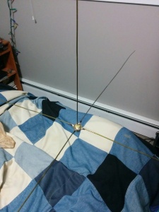
Last month I built my first antenna. It was a ground plane antenna constructed out of a UHF female jack panel mount connector (sometimes referred to as a SO-239, like this one) and approximately 10-gauge clothes hanger wire.

A ground plane antenna made from a panel mount UHF connector and 5 segments of clothes hanger wire.

A ground plane antenna made from a panel mount UHF connector and 5 segments of clothes hanger wire.

I also used a male UHF to female BNC adapter and built my own 10 ft coaxial cable with BNC connectors. I used RG-58 and these BNC connectors because they don’t require an expensive crimp tool.

The reason I built this antenna is that for years the Saskatoon Soaring Club has struggled establishing reliable radio communications between their winch and their gliders. It’s important to mention that at Cudworth (CJD2), we use 123.2 MHz for communications. What was happening is that while the glider is on the ground, the winch can “hear” the glider, but the glider can’t “hear” the winch. A hand held radio is used in the winch and a more powerful radio permanently mounted radio is used in the glider. Testing revealed that it was likely that the radiation pattern of the antenna on the winch poorly suited for the needs of the club (more details below). The solution was to build this ground plane antenna, since they have the radiation pattern required by the club.

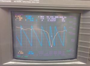
The old quarter wave antenna on the winch relied on using the metal roof of the cab as the “ground plane”. So long as the ground plane is sufficiently large (at least 1/4 wavelength in radius around the feed point of the antenna) the radiation pattern will be toroidal (donut shaped) and able to cover low elevation angles.Screenshot of spectrum analyzer At 123.2 MHz, a quarter-wavelength is approximately 60.9 cm (24 inches). Unfortunately, the amount of metal on the roof of the cab was insufficient (only about 20 cm). Theoretically this means that the resulting radiation pattern will be conically-tapered in elevation resulting in very little radiation being emitted at low elevation angles (low to the ground).  This document describes the problem in greater detail and shows that for real-world situations the radiation pattern is in fact more complicated than the naive description just given. In contrast, the ground plane antenna is built to include it’s own ground plane (see the 4 radials in the picture above). While searching for antenna solutions, I also stumbled upon the inverted L antenna, very cool.

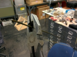
Cutting the vertical wireAfter building the antenna, I needed to tune it. Thankfully, I was allowed to use a network spectrum analyzer at work to do this. The antenna started at a resonant frequency of 98.995 MHz (with the vertical wire at a length of about 30 inches). Of course, tuning the antenna to a higher frequency required me to shorten the vertical wire and the radials. It was interesting to shorten the antenna wire by 2 inches at a time and observe the resulting change to the resonant frequency measured by the spectrum analyzer. By carefully trimming the wires of the antenna, I was able to tune it to a resonate frequency of 123.7 MHz with a bandwidth of approximately 20 MHz or so.

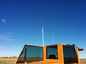
Finally, the antenna was tested in by mounting it to the winch. This was accomplished using U-bolts, tape, and 5 feet of PVC pipe.

The ground plane antenna temporarily mounted on the SSC's winch for real-world testing.

The ground plane antenna temporarily mounted on the SSC’s winch for real-world testing.

Testing was performed by first attempting to communicate with a grounded glider using the old antenna on the winch and then mounting the new antenna and attempting communication. As before, using the old antenna, 2-way communication could not be established, but when using the new antenna the problem was resolved!

The antenna works well and club members are very happy to be able to now communicate more easily with the winch. This has made the winch launching operation safer too.

Gliding with the Saskatoon Soaring Club

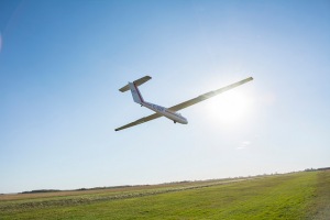
The SSC's L-23 coming in for a landing.

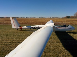
The SSC’s L-23 coming in for a landing.

This March I joined the Saskatoon Soaring Club (SSC) and started attending the glider ground school. Hearing gliding stories from John Toles who led the instruction only bolstered the excitement I felt about the prospect of learning to fly a glider (one of my favourites is how he was “beat by a bladder”). Little did I know the excitement I felt was only the beginning. My first flight was on May 9th at the Cudworth Aerodrome. It was a cool Saturday morning with clear skies and a light breeze. Fernando Garza was the Pilot in Command and we were flying in SSC’s Super Blanik L-23 (a beautiful glider with a wise and confident appearance). We launched via aerotow and on my first ever flight Fernando taught me how to do co-ordinated turns. On my third training flight I learned how to thermal as Fernando and I reached over 6000ft AGL!

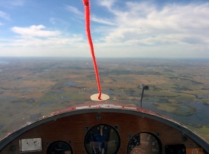
A view from the cockpit of the SSC's Schweizer SGS 1-26. This plane was built from a kit in 1956 and still flies like a champion.

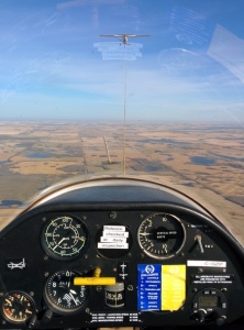
A view from the cockpit of the SSC’s Schweizer SGS 1-26. This plane was built from a kit in 1956 and still flies like a champion.

Since then I have managed a 52 minute solo flight from a release altitude of 1300ft AGL (and soared with Fernando who was in another glider) and I only need 3 more solo flights to get my glider pilot license. I have had the opportunity to fly solo in each of the club’s three gliders, the L-23, a Blanik L-33, and a Schweizer 1-26 (acquired this summer). It has been a fantastic summer!

As a final hurrah of this gliding season, some of us flew up to Birch Hills (CJD3) on a cross-country aerotow with the L-23. We visited with the Prince Albert Soaring Club and were able to fly winch launches in their K-7.

Gliding is an exhilarating and freeing experience. The raw mechanical feel of the glider enables the plane to somehow become an extension of yourself; as if you were the one with wings. Each flight provides the opportunity to learn and a chance to hone your skills. Gliding can also be a relaxing escape into the vertical

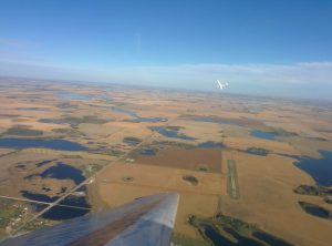
Fernando (in a Super Blanik L-23) and I (in a Schweizer 1-26, you can see my wing) soaring together 2500ft above Cudworth, SK.

Fernando (in a Super Blanik L-23) and I (in a Schweizer 1-26, you can see my wing) soaring together 2500ft above Cudworth, SK.

dimension, where far below one leaves the everyday things to be replaced with eagles and hawks (they show you where the thermals are!) and stunning views of the clouds and the prairie below. Perhaps more importantly, gliding is a social sport. It is about teamwork and camaraderie; we take pride in each other’s accomplishments. It’s a bit like joining a second family. Even though this gliding season is ending, the Club is making plans to keep active over the winter season. This is only the beginning of my gliding adventures!

Below you can see more pictures of the SSC gliders. If you are interested, I have an album on Flickr with even more photos.

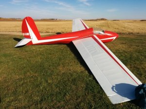
The Schweizer SGS 1-26 purchased this summer by the SSC.

The Schweizer SGS 1-26 purchased this summer by the SSC.

The L-33 Blanik Solo glider owned by the SSC.

The L-33 Blanik Solo glider owned by the SSC.

A cross-country aerotow from the low position. Heading to CJD3!

A cross-country aerotow from the low position. Heading to CJD3!

Members of the Prince Albert Soaring Club and the SSC with the Prince Albert Soaring Club's K7.

Members of the Prince Albert Soaring Club and the SSC with the Prince Albert Soaring Club’s K7.

ASUS z97-E/USB 3.1: Motherboard Sensors and Thermal Control on OpenSUSE 13.2

I recently put together a new desktop computer at work for data analysis for my supervisor. Here’s the parts list:

  • ASUS Z97-E/USB 3.1 motherboard
  • Intel i7-4790 processor
  • 32GB Crucial CAS 8 RAM
  • 2 Western Digital Black Series 1 TB HDDs
  • Rosewill Glacier 500M Power Supply
  • ASUS DVD Writer
  • NZXT S210-001 ATX Tower Case
  • Arctic Freezer 7 Pro CPU Fan/Heatsink

It’s a really solid processing machine and the Z97 is capable of clocking the RAM up to 1600MHz from 1333MHz using the built-in XMP. With water cooling, the Z97 could probably stably overclock the i7 up to 4.5 GHz (currently at 4 GHz). Since this machine will be used for heavy and prolonged computations, I wanted to make sure the fans were running sufficiently well to keep the i7 cool. To do this, we need to be able to monitor the fan speed and CPU temperature sensors.

The machine is running linux, specifically OpenSUSE 13.2. While I’ll focus on SUSE, this should work on any linux distribution so long as one uses the appropriate distribution specific commands. I am going to assume that the reader knows how to install software packages on SUSE 13.2. To read the CPU temperature and fan speeds, this is what I did:

1. Install lm-sensors

First I installed the lm-sensors package. The Z97-E has a Nuvoton NCT5538D that is used for fan speed measurements and control. In order for lm-sensors to read the NCT5538D we need to make sure the nct6775 kernel module is loaded (use modprobe nct6775 to immediately load it). To load the module on system start up we can either add nct6775 module to the /etc/modprobe.d/99-local.conf, or by running sensors-detect and following the instructions. If you use sensors-detect then you must make sure that the lm_sensors service is enabled and running:

systemctl enable lm_sensors
systemctl start lm_sensors

2. Modify grub Boot Options

Next we need to add the following to the GRUB_CMDLINE_LINUX_DEFAULT variable in the /etc/default/grub file: acpi_enforce_resources=lax (Many thanks to http://lists.lm-sensors.org/pipermail/lm-sensors/2014-November/042908.html for the tip). After modifying the file, we have to make sure that grub is updated by using: grub2-mkconfig -o /boot/grub2/grub.cfg.

3. Add an Entry to lm-sensors Config File (Fixed dead link: 6 December, 2015)

We now need to add an entry to the sensors configuration file. The nct6775 kernel module supports the NCT5538D chip via code for the Nuvoton NCT6791D, but we need to tell lm-sensors how to display the data it reads from the chip. Someone else already figured out the configuration for the Z97-A so I just used that and it seems to work. I added the entry discussed in the link for the Z97-A to the /etc/sensors3.conf file.

4. See If lm-sensors Works

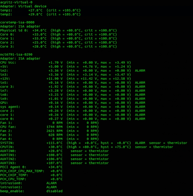
You may want to reboot the computer at this point. We can now test to see if lm-sensors is set up correctly. If it is, when we run the sensors command in a terminal, we should see something that looks like this:

sensors

Terminal output from executing the sensors command.

5. Optional: Set the Fan Speeds

First, BE VERY CAREFUL WITH THIS. You can easily damage your processor if you mess up the fan control. Also, it’s not my fault if you do.

Now we can modify the modes that the fan speeds will be adjusted with. For example, to set the fans to Smart Fan Mode 4, we can use a command like echo 5 > /sys/class/hwmon/hwmon3/pwm2_enable for each of the fans by replacing pwm2 with the appropriate number (see here for the location of the PWM for the fans and here for information on the supported fan modes for the nct6775 kernel module). Be VERY careful while doing this. I recommend having a terminal open running watch -n1 sensors so that you can monitor fan speed and CPU temperature while playing with the fan control. It took me some trial and error to figure out which pwm# controlled which fan. If you have any questions about this process, feel free to leave a comment.

Ubuntu 14.04 on a Macbook 2.1

The hard drive on an old white Macbook (v2.1) died recently so I went through the adventure of recovering data from it (needed to image the drive with dd conv=sync,noerror) and then reinstalling the OS. But I ran into some troubles with OS X 10.5. Some of the programs that one may like to use (e.g. Skype) are no longer supported and I would have had to buy the upgrade to at least 10.6. Rather than do that, I opted to install Ubuntu 14.04 instead.

First step in the installation was to burn a copy of Ubuntu 14.04 onto a DVD. Weird thing to do since I’m used the USB installation stuff that we typically now do. I grabbed the “64-bit Mac (AMD64) desktop” image DVD image file from here. It is important to grab the mac specific image because you may find the regular image will fail to install due to a firmware incompatibility with the EFI bootloader (lost the citation on this one). With the DVD in the Macbook, start it up and hold “c” to boot from the DVD.

The Ubuntu installation will be typical. Once finished, there’s a couple things you need to do post install:

  1. Install the mactel team’s fan support, otherwise you may notice your macbook fan runs at 100% all the time.
  2. Install the iSight firmware so that you can use your webcam. To do this, you must:
    1. Grab the firmware file (AppleUSBVideoSupport) from here (remove the .pdf first, wordpress wouldn’t let me host it without), or if you have a Mac OSX 10.4 or 10.5 installed, you can get the firmware file at:
      /System/Library/Extensions/IOUSBFamily.kext/Contents/PlugIns/AppleUSBVideoSupport.kext/Contents/MacOS/AppleUSBVideoSupport
    2. Make sure you know where you’ve downloaded/copied the AppleUSBVideoSupport to.
    3. Install the iSight firmware tools with: sudo apt-get install isight-firmware-tools. This will cause the software to ask for the path to the firmware file. If you have it on your desktop, the path would be /home/username/Desktop/AppleUSBVideoSupport.
    4. Reboot, and you are done!
  3. That’s it! Everything else seems to work just fine right out of the box.

Now one can get more life out of that Macbook without having to spend any cash on upgrading OS X.

Why doesn’t my NES Zapper work?

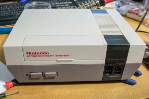
When I was around 4-5 years old I remember playing on a NES while over at friends’ of my parents. Growing up, the classic NES titles like Super Mario Bros., Duck Hunt, Super Mario Bros. 3, etc., and now that I’m “an adult” I have my very own NES. The only problem is that I recently discovered that I couldn’t play Duck Hunt! The game cartridge works perfectly fine and I even have an old analogue CRT TV that is compatible with the NES Zapper, but for some reason (as you will learn as I did) the gun didn’t work when I would fire up a Duck Hunt session.

Diagnosis

The first thing I did was check Google to see if anyone else encountered this problem. Most of the results pertained to issues with getting the Zapper to work with LCD TVs, (not my problem, but to understand why it doesn’t work with LCDs, you can checkout out the Wikipedia article) so I disassembled the Zapper’s connector and connected a multimeter to monitor the voltage levels when the Zapper was connected to the NES.

 nes nes_zapper

The measurements revealed that when the trigger was pulled, the voltage on pin D4 (bottom left pin of the picture where I’m holding the connector) of the NES controller connector didn’t rise to 5V from 0V; instead, the voltage would stay at 5V and very slowly decay. I decided to take apart the Zapper to see if it was the problem (and because I wanted to see how it worked!).

 nes_connector4 nes_connector
nes_connector3 nes_connector2

If you have ever used a Zapper, you may have noticed (or maybe not) how well balanced the controller feels in your hand. As you can see in the picture, the Zapper has a metal weight in the handle that helps balance the controller. There is also a lens and metal collimator in the barrel of the Zapper. Well actually the whole barrel is really a collimator and the metal collimator probably acts as another weight to help balance the controller.  Finally there is the trigger mechanism and the Zapper circuit. The Zapper circuit handles detection of trigger pulling and whether or not the user has “hit” the target in Duck Hunt.

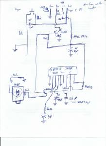
zapper_circuit

I mapped out the circuit (very roughly…) and found that the circuit is really two circuits in one: 1) a trigger circuit with a 10uF de-bouncing capacitor, and 2) some kind of circuit that decodes input from a PD 43Pi photodiode, used to detect if a duck has been hit or not, using an IR3T07A chip (couldn’t find the datasheet!), and the output from this chip is inverted using a 2SC458 NPN transistor. This output is sent to the NES through the D3 pin.

inside_zapper zapper_circuit
zapper_circuit3 zapper_circuit2

Testing of the Zapper circuit determined that it was working. I checked the capacitors and resistors and they all seemed to be ok. I also checked to see if varying the intensity (brightness) of light on the photodiode varied the voltage output on pin D3 (the pin right above D4) and it did change as expected; the brighter the light, the larger the voltage. These results suggested that there must be a problem with the NES, so I put the Zapper back together and connected it to the player 1 port on the NES. Pulling the trigger showed that the voltage on D4 would jump from 0V to 5V to 0V as it should! So the problem was with the player 2 port on the NES. At this point, I also found a website with a nice circuit diagram and description of the Zapper gun.

The Fix

nes_port2

When I opened up the NES, the problem was immediately obvious. As you can see in the picture, for some reason, one of the wires wasn’t connected to the player 2 port on the NES! As you might expect, after connecting this wire to the port and re-assembling the NES the Zapper gun worked!

Now I can relive my childhood nostalgia and contribute to virtual duck murder unabated!

working_zapper

Using Photoshop and Netflix on Ubuntu 13.04 *Updated*

Update: The following also works on Ubuntu 14.04.

My favourite operating system to use is Ubuntu. Like most people, I grew up using Windows, but seven years ago I started experimenting with Linux while trying to build a webserver. I had an old machine that could manage Debian 3.0 or 3.1 (can’t remember which) and set up Apache on it without the ability to use a GUI. Since building the webserver, I have been moving closer and closer to independence from Windows.

My laptop and desktop computers currently dual boot Windows 7 and Ubuntu 13.04, but I only really logged in to Windows to use Photoshop or to watch Netflix. Recently, thanks to the wonderful work of some excellent people in the Linux community, it is possible to  completely switch from Windows to Linux without sacrificing the use of Photoshop or Netflix!

Netflix on Ubuntu/Debian

This is actually very easy to do so I won’t elaborate much here. Basically you can just go here and follow the instructions. TL;DR installation amounts to:

sudo apt-add-repository ppa:ehoover/compholio
sudo apt-get update
sudo apt-get install netflix-desktop

and then you are done! Wooo!

Photoshop CS6

There are a number of resources online that explain how to install Photoshop in Linux, but my experience trying to install a legitimate copy of CS6 was difficult at best. After a few hours of fiddling, I managed to get it to work. Hopefully my guide will save some time for someone else. Before we start keep in mind that I have only tried this on Ubuntu 13.04 and I will be assuming that you have not installed wine before. I am also assuming that all commands are executed in your home directory.

Installing Wine

First we must install wine. You can do this on the command line via the commands:

sudo add-apt-repository ppa:ubuntu-wine/ppa
sudo apt-get update
sudo apt-get install wine1.5

This should also install a little handy tool called winetricks. You can double check with a:

sudo apt-get install winetricks

Configuring Wine

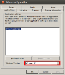
Next we need to configure wine to emulate Windows XP in 32 bit mode. We do this by running the command:

WINEARCH=win32 WINEPREFIX=~/.wine winecfg

and then change the windows version to “Windows XP”.

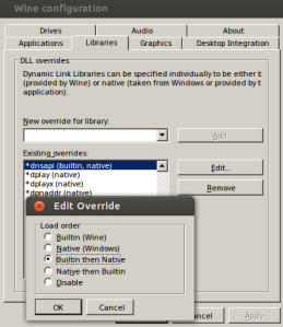
Change the windows version to "Windows XP".Make sure that the dnsapi library is set to "Builtin then Native".

Winetricks

Next we must use winetricks to install many different libraries and programs required to run Photoshop. Use the following commands on the command line:

winetricks -q amstream cc580 directx9 d3dx11_42 d3dx9_43 d3dx11_43 dinput dinput8 gecko vcrun2005 vcrun2008 vcrun2010 xact
winetricks -q atmlib gdiplus ie6 vcrun2005sp1 vcrun2008 fontsmooth-rgb corefonts msxml3 msxml6 winhttp wininet

odbc32.dll and odbcint.dll

Next we need to place 2 .dll files in the system32 folder of our wine installation. The .dll files can be downloaded here. Assuming we are in the home directory, we use the following two commands:

cp ~/odbc32.dll ~/.wine/drive_c/windows/system32/
cp ~/odbcint.dll ~/.wine/drive_c/windows/system32/

dnsapi.dll

After copying the .dll files, the next thing to do is the make sure that the correct version of dnsapi.dll is used. To do this we must once again enter the wine config:

winecfg

Navigate to the “Libraries” tab and look for “*dnsapi”  in the list of libraries. Once found, click edit and then make sure to set the “Builtin then Native” radio button.

Installing Photoshop

Finally, we can now install Photoshop. Insert your CD and then execute the “Set-up.exe” file on the CD. Follow along the instructions on the installer window. Once you get to the installing process, it should fail, but have no fear, because for some strange reason, Photoshop will still install in the background in spite of the error window. Do not close the error window until you are absolutely sure Photoshop has had enough time to install (for me this took almost 10 minutes). You have not installed Photoshop on Ubuntu!